LAPEYRE®
STAIRS
|
|
|
|
|
|
|
|
|
|
|
|
ALTERNATING
TREAD
|
|
|
|
|
|
|
|
|
|
|
|
The
Lapeyre® stair is safer than vertical ladders and ships ladders |
|
|
|
|
|
|
|
|
|
|
|
STEEL
STAIRS
|
|
|
|
|
|
|
|
|
|
|
|
|
 |
|
 |
|
|
 |
|
 |
|
|
|
|
|
|
|
|
|
|
|
|
|
|
|
|
|
|
Materials
& Finishes:
Carbon Steel
• Safety Yellow Powder Coat
• Gray Primer Powder Coat
• Iron Gray Powder Coat
• 180 additional Powder Coat Colors available
• Hot Dip Galvanized
Stainless Steel
• Natural
Finish
Heights: Custom Height built
56 Degree
• 36" to
240"
68 Degree
• 42" to 240"
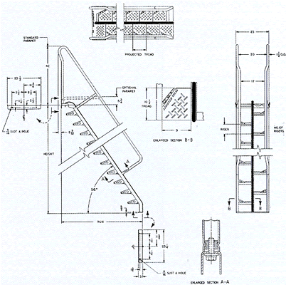
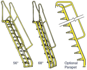
A flush or an optional 5.75" handrail is available
for roof hatch applications. |
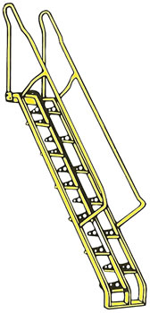
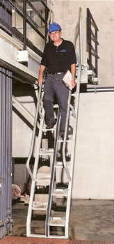
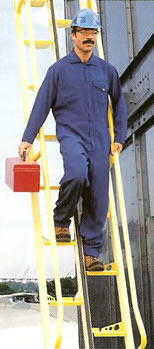
The
Lapeyre® stair features a unique alternating
tread design which provides greater tread depth
than vertical ladders or ship's ladders. This design
allows comfortable face forward descents at steep
angles. The stair includes close fitting handrails
which provide support and a cushioned central
stringer which virtually eliminates the possibility of
hitting the nosing of a tread. |
|
|
|
|
|
|
|
|
|
|
 |
|
|
|
|
|
|
|
|
|
 |
|
56°
AND 68° STEEL |
|
|
SEE
BELOW FOR PRICES |
|
|
|
ALUMINUM
STAIRS
|
|
|
|
|
|
|
 |
|
|
|
 |
|
|
|
|
|
|
|
|
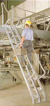
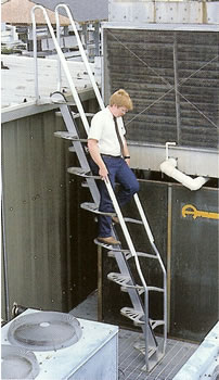
The Lapeyre® aluminum
alternating tread stair combines the safety features of
our unique, alternating tread design with the advantages aluminum has
to offer.
Aluminum is ideal for exterior applications and for applications where
weight is
a consideration. The cast aluminum treads are welded to the central stringer
and
to the handrails, creating an all-in-one welded unit. An optional 3.75"
handrail
is available for roof hatch applications. |
|
|
|
|
|
|
|
 |
|
|
|
Materials
& Finishes:
Aluminum
• Natural Finish
Heights:
Custom Height built
68 Degree
• 24" to 216" |
|
|
|
|
|
|
 |
|
Order
Online, by Phone, or by E-Mail |
|
|
|
~ Add
items to your online shopping cart ~
Click a Price of the item you wish to purchase. |
|
|
PRICES
FOR STEEL AND ALUMINUM STAIRS |
VERTICAL
RISE |
PROJECTIONS SHOWN
IN INCHES FOR: |
Carbon Steel
Yellow or Iron
Gray Powder
Coat Finish
56/68 Degree |
Carbon Steel
Hot-Dip
Galvanized
56/68
Degree |
*Carbon Steel
Choice of
Color
Powder
Coat 56/68
Degree |
Aluminum
Natural
Finish
68 Degree |
Stainless Steel
Natural Finish
56/68 Degree |
| IN |
IN |
56 DEGREE |
68
DEGREE |
68
DEGREE |
| FEET |
INCHES |
STEEL |
STEEL |
ALUMINUM |
| 2 |
24 |
N/A |
N/A |
15.86 |
N/A |
N/A |
N/A |
|
N/A |
| 2.5 |
30 |
N/A |
N/A |
18.49 |
N/A |
N/A |
N/A |
|
N/A |
| 3 |
36 |
28.93 |
N/A |
20.31 |
|
|
$1,904.95 |
|
|
| 3.5 |
42 |
33.11 |
23.08 |
22.97 |
|
|
$2,083.57 |
|
|
| 4 |
48 |
37.25 |
25.66 |
25.56 |
|
|
$2,262.18 |
|
|
| 4.5 |
54 |
41.37 |
28.2 |
28.1 |
|
|
$2,440.80 |
|
|
| 5 |
60 |
44.91 |
30.28 |
30.18 |
|
|
$2,619.42 |
|
|
| 5.5 |
66 |
49.07 |
32.83 |
32.73 |
|
|
$2,798.03 |
|
|
| 6 |
72 |
53.21 |
35.36 |
35.26 |
|
|
$2,976.65 |
|
|
| 6.5 |
78 |
57.33 |
37.86 |
37.76 |
|
|
$3,155.26 |
|
|
| 7 |
84 |
61.44 |
40.04 |
39.94 |
|
|
$3,333.88 |
|
|
| 7.5 |
90 |
65.15 |
42.56 |
42.46 |
|
|
$3,512.49 |
|
|
| 8 |
96 |
69.27 |
45.05 |
44.95 |
|
|
$3,691.11 |
|
|
| 8.5 |
102 |
73.39 |
47.28 |
47.18 |
|
|
$3,869.72 |
|
|
| 9 |
108 |
77.49 |
49.78 |
49.68 |
|
|
$4,048.34 |
|
|
| 9.5 |
114 |
81.59 |
52.27 |
52.17 |
|
|
$4,226.95 |
|
|
| 10 |
120 |
85.38 |
54.75 |
54.65 |
|
|
$4,405.57 |
|
|
| 10.5 |
126 |
89.49 |
57.01 |
56.91 |
|
|
$4,584.18 |
|
|
| 11 |
132 |
93.59 |
59.5 |
59.4 |
|
|
$4,762.80 |
|
|
| 11.5 |
138 |
97.68 |
61.98 |
61.87 |
|
|
$4,941.42 |
|
|
| 12 |
144 |
101.77 |
64.45 |
64.35 |
|
|
$5,120.03 |
|
|
| 12.5 |
150 |
105.62 |
66.74 |
66.64 |
|
|
$5,298.65 |
|
|
| 13 |
156 |
109.71 |
69.21 |
69.11 |
|
|
$5,477.26 |
|
|
| 13.5 |
162 |
113.8 |
71.68 |
71.58 |
|
|
$5,655.88 |
|
|
| 14 |
168 |
117.89 |
73.98 |
73.88 |
|
|
$5,834.49 |
|
|
| 14.5 |
174 |
121.97 |
76.45 |
76.35 |
|
|
$6,013.11 |
|
|
| 15 |
180 |
125.85 |
78.92 |
78.82 |
|
|
$6,191.72 |
|
|
| 15.5 |
186 |
129.94 |
81.38 |
81.28 |
|
|
$6,370.34 |
|
|
| 16 |
192 |
134.02 |
83.7 |
83.6 |
|
|
$6,548.95 |
|
|
| 16.5 |
198 |
138.11 |
86.16 |
86.06 |
|
|
$6,727.57 |
|
|
| 17 |
204 |
142.19 |
88.62 |
88.52 |
|
|
$6,906.18 |
|
|
| 17.5 |
210 |
146.09 |
91.08 |
90.98 |
|
|
$7,084.80 |
|
|
| 18 |
216 |
150.17 |
93.41 |
93.31 |
|
|
$7,263.42 |
|
|
| 18.5 |
222 |
154.25 |
95.87 |
N/A |
|
|
$7,442.03 |
N/A |
|
| 19 |
228 |
158.33 |
98.33 |
N/A |
|
|
$7,620.65 |
N/A |
|
| 19.5 |
234 |
162.4 |
100.78 |
N/A |
|
|
$7,799.26 |
N/A |
|
| 20 |
240 |
166.32 |
103.12 |
N/A |
|
|
$7,977.88 |
N/A |
|
|
| *Contact
us for Optional Color Charts. |
|
SAFETY
GATES
|
|
|
|
 |
|
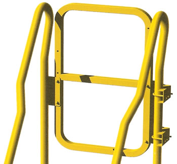
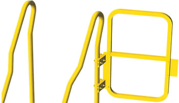
If
you have been searching for a way to provide add-
itional safety at the top of your alternating tread stair,
we now have the answer. Our new safety gate attaches
to the top rails of our alternating tread stairs. This is the
first gate designed with the dimensions and connections
needed to provide a perfect fit on an alternating tread
stair. Completely reversible, the gate swings 180° and
has several installation options. It attaches to the stair
handrails or to the platform at the top of the stair. You
will only find this model gate by calling Lapeyre Stair
as it is manufactured exclusively for us by PS Doors.
Specifications:
• Mounting Bracket: PS DOORS standard, exclusive
Universal Pivot Clamp Bracket to fit railings up to 2"
OD.
• Hinge Plate: Mounting holes for reversible swing
adjustment.
• Hinge
Springs: Torsion type, stainless steel. Provide
two (2) springs per gate, housed within hinge pivot.
• Gate
Arm: Formed
1-1/4" square, 11 gauge steel
tubing with center rail.
• Material Finishes:
-Carbon Steel, on all
exposed surfaces. Choose
from options below:
1. Powder Coat Safety Yellow. Fasteners to
be
zinc plated.
2. Hot Dip Galvanized. Fasteners to
be zinc plated.
-Stainless Steel, grade 304, mill finish, acid washed and
rinsed after fabrication, interfering welds are
ground,
not polished. Fasteners to be stainless steel.. |
|
|
 |
|
|
|
|
|
|
|
|
 |
|
Order
Online, by Phone, or by E-Mail |
|
|
|
~ Add
items to your online shopping cart ~
Click a Price of the item you wish to purchase. |
|
|
| MODEL NUMBER |
Shipping Weight |
Unit Price |
| LSG-3-18-GAL |
24 lbs |
|
| LSG-3-18-PCY |
24 lbs |
|
| LSG-3-18-SST |
24 lbs |
|
|
|
|
|
Dimensions:
• Gate Width: 18"
• Overall
Vertical Height: 30-1/4"
Gate Operation:
• Allows for 180° travel.
• Gate swing is reversible by
repositioning Gate
Hoop on Hinge Plate. |
Finish
Identifier:
GAL = Galvanized
PCY = Powder Coat Safety Yellow or Gray Primer
SST = Stainless Steel |
|
|
|
|
|
|
INSTALLATION
DETAILS |
1.
When ordering, specify the change in elevation (H) between the upper finished
floor surface where the top landing will
attach (A) and the lower finished floor
surface where the foot of the stair will be
secured (B). Be sure to take into account
the effects of a slopping lower floor. |
|
2.
A minimum of 6" (15.24 cm) should be
provided between the handrails and any
other object (a minimum of 12" (30.48 cm)
between handrails on two adjacent stairs).
More than 6" (15.24 cm) is preferred to
allow easier carrying of small objects out-
side the handrails. |
|
3. Always install
the stair with the top
tread at same elevation as the upper
finished floor or roof surface. For wall
parapets, contact us.
4. The stair is secured
in place by bolts
(not included) at top and bottom. |
|
|
|
|
|
|
|
|
|
 |
|
|
|
|
|
SPECIFICATIONS |
|
|
SECTION
05517 - ALTERNATING TREAD STEEL STAIRS
PART
1 - GENERAL
1.1 RELATED DOCUMENTS:
Drawings and general provisions of Contract, including General
and Supplementary Conditions and Division-1 Specification
sections, apply to work of this section.
1.2 SUMMARY:
A. Provide all material, labor, equipment and services and perform
all operations necessary or required for the work of this section,
in accordance with the Drawings and Specifications, and including fabrication
and installation of Alternating Tread Steel Stairs.
B. Related work specified elsewhere includes but is not limited to:
1. Conventional Metal Stairs in another Division 5 section
2. Metal Fabrications in another Division 5 section
3. Painting in Division 9
1.3 PERFORMANCE REQUIREMENTS:
A. Stair Treads: shall be capable of withstanding a single
concentrated 1000 pound load without permanent deformation.
B. Handrail: shall be capable of withstanding a single
concentrated load of 200 pounds or a uniform load of 50 pounds
per linear foot applied in any direction at any point on the rail.
1.4
CONSTRUCTION REQUIREMENTS:
A. Landings,
Treads, and Mounting Base: shall be stamped
and formed from single piece material. Stock shapes, hand forming,
or welded remnants shall not be permitted. All stamped parts
shall have integrally formed rigidizing bends and shall be spot
welded to stringers of like material.
B. Welds: shall be a minimum of 6 welds per tread, and 12 welds
each on the landing and footing. Each weld shall be quality
controlled and be capable of withstanding a minimum of
2800 lbs. in shear.
C. Pedestrian Surfaces: shall be punched through with upset
non-skid openings.
D. Riser Spacing: shall be equally spaced to within 3/16" for
adjacent risers and to within 3/8" for any two non-adjacent
risers on a stair.
E. Handrails: shall be contoured for body guidance and underarm
support and shall be attached to the outside stringers and
landings by bolting.
F. Landing Reinforcement: shall be with minumin .20" (0.51 cm)
steel formed angle notched and punched and factory welded to
the landing at the points of a handrail attachment.
G. Rubber Foot Divider: shall be affixed to the central portion
of the landing. A rubber bumper strip shall be attached or will be
provided for field attaching to the central stringer.
1.5
DIMENSIONS:
A. Stair Angle:
[56] or [68] degrees from horizontal as specified
in the drawings.
B. Vertical Drop: the change in elevation, as shown in the drawings,
between the upper finished floor surface where the top landing
will be attached and the lower finished floor surface where the
base of the stair will be secured.
1.6
SUBMITTALS:
Dimensional Prints: shall be submitted for approval prior to
fabrication.
PART 2- PRODUCTS
B. Substitutions will not be considered.
2.2
MATERIALS:
A. Carbon Steel:
1. Treads: 13 Gauge 1010/15 HRPO per ASTM A569
2. Landing & Foot Stampings: 11 Gauge 1010/15 per ASTM A569
3. Stringers:
a. 2" x 1 3/4" x 11 Gauge 1010/15 per ASTM A569 for 56 degree
stairs under 10 vertical feet and for 68 degree stairs under 12
vertical feet.
b. 3" x 1 3/4" x 11 Gauge 1010/15 for 56 degree stairs over
10
vertical feet and for 68 degree stairs over 12 vertical feet.
4. Handrails: 1 1/2" OD x 0.083" 1010/15 CS per ASTM A569
cold drawn, fully annealed tube per ASTM 513.
B. Stainless Steel:
1. Treads: 13 Gauge 304 SS
2. Landing & Foot Stampings: 11 Gauge 304 SS
3. Stringers:
a. 2" x 1 3/4" x 11 Gauge 304 SS for 56 degree stairs under
10
vertical feet and for 68 degree stairs under 12 vertical feet.
b. 3" x 1 3/4" x 11 Gauge 304 SS 56 degree for stairs over 10
vertical feet and for 68 degree stairs over 12 vertical feet.
4. Handrails: 1 1/2" OD x 0.065" 304 SS cold drawn, fully
annealed tube per ASTM A513.
C. Miscellaneous Material:
1. Rubber Spine: Hollow neoprene
2. Rubber Foot Divider: Solid neoprene
2.3
FINISHES:
A. Carbon Steel:
1. Safety Yellow Paint: Powder Coat Baked Enamel or
2. Hot-Dip Galvanized: per ASTM A123
B. Stainless Steel: Natural finish
2.4
FABRICATION:
General: Fabricate alternating tread steel
stairs to conform with performance and construction
requirements, and in accordance with approved shop drawings
or dimensional prints. Fabricate and shop-assemble to greatest
extent possible.
A. Carbon Steel: gas metal arc welded with treads spot welded to stringers
and bolt-on handrails with included bolts using the
specified materials.
B. Stainless Steel: gas tungsten arc welded and/or gas metal
arc welded with treads spot welded to stringers and bolt-on
handrails with included bolts using the specified materials.
PART
3- EXECUTION:
3.1 PREPARATIONS:
A. Coordination:
Coordinate start and installation of steel
alternating treads with all other related and adjacent work.
Installation shall not start until the construction
has progressed to the point that weather conditions and
remaining construction operations will not damage stair
installation.
B. Verification: Verify that dimensions and angle are correct
and that substrate is in proper condition for stair installation.
Do not proceed to install until all necessary corrections have
been made.
3.2
INSTALLATION:
A. If bumper
has not been installed at the factory, install the self adhesive bumper.
B. Prepare mounting holes.
C. Position stair with top tread at same elevation as upper
finished floor or roof surface.
D. Secure stair with not less than 2 bolts or studs at top and
with not less than 2 at bottom of stair.
E. Touch up with matching paint any chipped or abraded
damage to factory finish or
F. Touch up any damage to galvanized surfaces using
galvanized repair paint in accordance with ASTM A780.
3.3
CLEAN:
Leave work area clean and free of debris. |
SECTION
05 51 6- ALTERNATING TREAD ALUMINUM STAIRS
PART 1- GENERAL
1.1
RELATED DOCUMENTS:
Drawings and
general provisions of Contract, including General
and Supplementary Conditions and Division-1 Specification
sections, apply to work of this section.
1.2
SUMMARY:
A. Provide
all material, labor, equipment and services and
perform all operations necessary or required for the work of this section,
in accordance with the Drawings and Specifications,
and including fabrication and installation of Alternating Tread
Aluminum Stairs.
B. Related work specified elsewhere includes but is not limited to:
1. Conventional Metal Stairs in another Division 5 section
2. Metal Fabrications in another Division 5 section
1.3
PERFORMANCE REQUIREMENTS:
A. Stair Treads: shall be capable of withstanding a concentrated
1000 pound load without permanent deformation..
B. Handraisl: be capable of withstanding a load of 200 pounds
applied in any direction at any point on the rail.
1.4
CONSTRUCTION REQUIREMENTS:
A. Cast Aluminum
Treads, Landings, and Mounting Base: shall be shielded metal arc welded
to a single extruded box-like stringer.
B. Tread Castings: shall have integrally cast handrail support arms which
are precision machined and welded to continuous aluminum handrails.
C. Pedestrian Surfaces: shall be cast with skid resistant surfaces
and all treads shall have upturned integrally cast skid barriers.
D. Riser Spacing: shall be equally spaced to within 3/16" for
adjacent and to within 3/8" for any two non-adjacent risers on
a stair.
E. Handrails: shall be contoured for body guidance and underarm support,
and shall have inclined hand side portions for free
sliding of the hands unimpeded by the handrail supports.
F. Cast Aluminum Foot Divider: shall be an integral part of the
landing and shall form a support for a rubber bumper strip that
shall be attached to the central stringer.
1.5
DIMENSIONS:
A. Stair Angle: 68 degrees from horizontal
B. Vertical Drop: the change in elevation, as shown in the
drawings, between the upper finished floor surface where the
top landing will be attached and the lower finished floor surface
where the foot of the stair will be secured.
1.6 SUBMITTALS:
Dimensional prints shall be submitted for approval prior
to fabrication.
PART
2-PRODUCTS
B. Substitutions
will not be considered.
2.2
MATERIALS:
A. Landings, Treads and Foot Castings: Aluminum alloy F356F
B. Handrails:
1. Aluminum Alloy 6063-T4 per ASTM B221
2. 1-1/2" x 1/8" Tube
C. Central Stringer:
1. Aluminum Alloy 6063-T52 per ASTM B221
2. 1-3/4" x 4" x 1/8" Box Shape
D. Miscellaneous Materials:
1. Rubber Spine: Hollow neoprene strip
2.3
FINISH: Natural
Finish
2.4
FABRICATION:
A. General:
Fabricate alternating tread aluminum stairs to
conform with performance and construction requirements,
and in accordance with approved shop drawings or
dimensional prints. Fabricate and shop-assemble to greatest
extent possible.
B. Fabricate gas metal arc welded and/or gas tungsten arc welded alternating
tread aluminum stairs using the specified materials.
PART 3- EXECUTION:
3.1
PREPARATIONS:
A. Coordination: Coordinate start and installation of aluminum alternating
treads with all other related and adjacent work.
Installation shall not start until the construction has progressed
to the point that weather conditions and remaining construction
operations will not damage stair installation.
B. Verification: Verify that dimensions and angle are correct
and
that substrate is in proper condition for stair installation. Do not
proceed to install until all necessary corrections have been made.
3.2
INSTALLATION:
A. Prepare
mounting holes.
B. Position stair with top tread at same elevation as upper
finished floor or roof surface.
C. Secure stair with not less than 2 bolts or studs at top and
with not less than 2 at bottom of stair.
3.3
CLEAN:
Leave
work areas clean and free of debris. |
|
|
Lapeyre Stairs, Alternating
Tread, Steel Stiars, Alternating Tread Design, Close Fitting Handrails,
Stainless Steel,
Aluminum Stairs, and Alternating Tread Stair from your complete source
for material handling equipment. |
|

